Print-in-place feels like the obvious win: no assembly, no glue, no lost parts, the thing comes off the plate and moves. Then a hinge that should have flexed cracks on the third bend, a ball joint that should have clicked is welded solid, and the arm that should have been strong snaps at a layer line. Every one of those is a joint that was printed in the wrong direction because the whole model had to share one direction.
Short version: a joint has a gap and a flexing element, and each of them has a good direction and a bad one relative to the layers. Print-in-place gives every joint in the model the same direction; separate snap-together parts let each joint pick its own. Choose print-in-place when all the joints agree on a direction, which is chains and flat hinges. Choose separate parts when they don't, which is almost every posable figure.
The gap has a direction
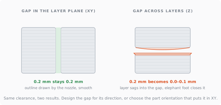
FDM builds in layers, so a part is not the same object in all directions. In the horizontal plane the nozzle draws a smooth, accurate outline. Vertically the surface is a staircase of layers, and the first few layers spread outward under the hot nozzle by 0.1 to 0.4 mm, the elephant foot (Prusa's compensation guide). A 0.2 mm gap therefore means two different things: measured sideways it is 0.2 mm, measured vertically it is 0.2 mm minus the sag of the layer bridging it minus the foot at the bottom, which can be nothing at all.
That is the reason a print-in-place chain works lying flat and fuses standing up. Lying flat, every gap between segments is a horizontal slot printed by the outline, clean. Standing up, the same gaps are vertical, and the lowest one closes on layer one.
The flex has a direction too
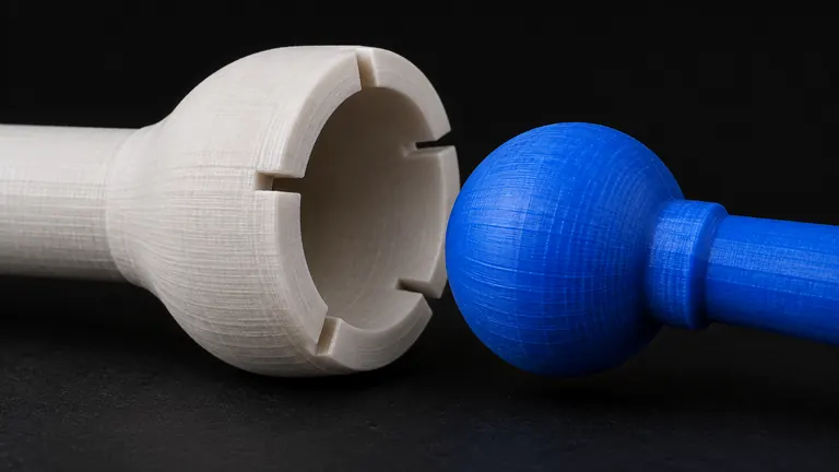
A snap joint works because something bends: a cantilever tab, the two halves of a ball socket, the lip of a lid. Printed plastic bends fine along its layers and cracks across them. Measured on PLA, a sample built upright reached 35.5 MPa against 55.5 MPa for one built flat, about 64% (Eryildiz, 2021); design guides say the same in words, avoid building a snap in the Z direction because layer bonding lowers strength and raises fracture risk (Protolabs Network). So the tab or the socket slits must lie in the layer plane, where bending stretches a line of plastic instead of pulling two layers apart.
Now put both rules on one figure. The shoulder socket wants its slits horizontal, so the torso prints upright. The elbow hinge wants its pin horizontal, so the arm prints lying down. The tail chain wants to lie flat. Three joints, three orientations, one plate. Print-in-place has to pick one and lose two.
What each approach is good at
| Print-in-place | Separate parts that snap | |
|---|---|---|
| Orientation | one for the whole model | one per part, each chosen for its joint |
| Gap | must survive vertical printing where it is vertical | can always be put in the horizontal plane |
| Flexing element | wherever the single orientation leaves it | always in the layer plane |
| Ball joints | rarely; the throat can't be printed closed | the natural home |
| Multi-color | one part, color by region only | each part its own filament, no AMS needed |
| Assembly | none | minutes, with a chance to get it wrong |
| Small parts | none to lose | keep every removable piece above 31.7 mm for kids |
| Fits over 256 mm | no | yes, that's what splitting is for |
| Scaling | breaks the joints | breaks them the same way, but they can be regenerated |
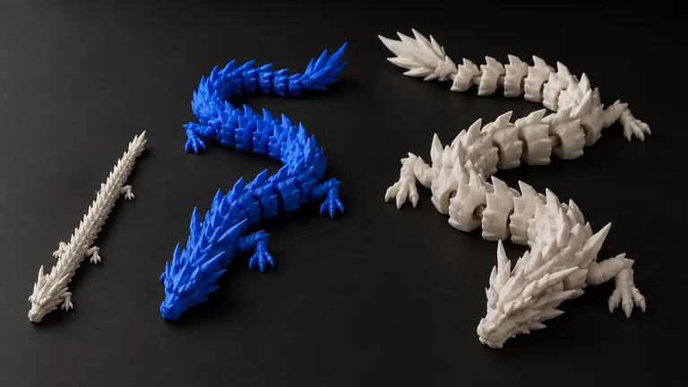
Where print-in-place shines is exactly where its constraint costs nothing: a flexi dragon whose every hinge shares one horizontal axis, a flat living hinge, a chain of segments. The articulated crystal dragon by Saber3D, with tens of thousands of boosts on MakerWorld, is print-in-place because it is one long chain lying on its side. A posable figure with shoulders, elbows and a turning head is the opposite case.
The tax on separate parts
Separate parts pay in a different currency: accumulated error. Every fit carries a tolerance of roughly ±0.1 to 0.2 mm, and a chain of four parts stacks four of them, so the hand can end up 0.4 to 0.8 mm from where the model put it. The remedies are standard machine-design practice: one datum part, usually the torso, from which everything else is referenced, and compliant fits in between so the error is absorbed rather than accumulated. How to size and key the pins so the fits don't fight each other is in alignment pins for split prints →. Bambu's own guidance for cut models adds a practical rule: print all the pieces with the same layer height and the cut faces flat on the plate where possible (Bambu Lab wiki).
Where to put the cut so the seam between the parts disappears is its own subject: where to cut a 3D model →.
What we chose for the constructor
For the constructor we're building into PHORM, the first version produces separate parts with hidden snap joints rather than print-in-place. The reason is this article: each piece gets its own best orientation, every gap can be put in the horizontal plane, every socket slit in the layer plane, and clearances can be set per printer and material at the final size. Flexible tails and chains are the one place we keep the print-in-place approach, as separate links that snap together but print flat like a flexi. Both start from a single watertight model with real dimensions, the thing a generation gives you today (generate one from a photo →).