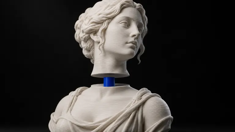
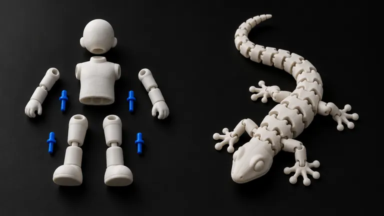
You split the model, added two neat round pins on one half and two round holes on the other, printed both, and the halves don't go together. Or they go together with a mallet. Or they go together and rock. You open the clearance by 0.1 mm and now they rock more. This is not a calibration problem. Two round pins are a design problem, on every printer that has ever existed.
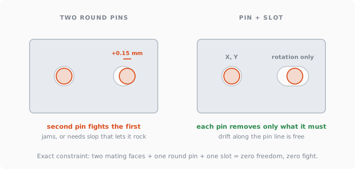
Short version: a fit should remove exactly the freedoms it needs to remove and no more. One round pin fixes position; the second one fixes rotation, and for that it only needs to stop sideways movement, so it should be a slot, not a hole. Two round holes fight over the same job, and any drift in the print, ±0.15 mm is normal, turns the fight into a jam or a wobble.
The rule, in one paragraph
A rigid part has six degrees of freedom: three translations, three rotations. Two mating faces already take three of them away, leaving two slides and one spin in the plane of the seam. A round pin in a round hole removes the two slides. All that is left is the spin, and a slot, a hole stretched along the line between the two pins, removes exactly that while leaving the second pin free to sit anywhere along that line. Machine designers call this exact constraint; Blanding's book of that name is the standard reference (Exact Constraint, ASME 1999). A second round hole tries to remove the slides a second time. If the two pin centers on part A are 0.15 mm further apart than the two hole centers on part B, the pins cannot both enter, and 0.15 mm is a normal day for FDM (the fit table →).
Sizes that work in PLA
| Feature | Value | Why |
|---|---|---|
| Pin diameter | 4 mm or more | a 3 mm pin is seven nozzle lines and breaks at the seam |
| Pin length | 1.5 to 2 × diameter | shorter tilts, longer binds |
| Clearance, press fit | 0.05 to 0.15 mm per side | held by friction, taken apart rarely |
| Clearance, slide fit | 0.2 to 0.3 mm per side | glued or clipped after assembly |
| Slot | pin diameter + clearance wide, + 0.5 mm long | absorbs the drift along the pin line |
| Chamfer on every mating edge | 45°, 0.3 to 0.5 mm | hides the gap, kills the elephant foot, self-centers |
| Lead-in on the pin tip | 30° or more, 0.5 mm | finds the hole without fingers holding it |
| Crush ribs in a press-fit hole | three ribs, 0.3 to 0.4 mm tall | grip without needing precision |
Crush ribs deserve a word. Instead of drilling the hole to an exact interference, model it slightly oversized and add three tiny ridges along its length. The pin crushes the ridges on the way in, so the joint is tight whatever the printer did that day. It is how injection-molded parts have handled the same problem for decades.
The chamfer is not decoration. The first layers of every print spread outward by 0.1 to 0.4 mm (elephant foot), and if the cut face was on the plate, that foot sits exactly on the mating edge and holds the halves apart. A 0.4 mm chamfer removes the foot and turns the seam into a fine groove that reads as a panel line instead of a crack; why that reading matters is in where to cut so the seam disappears →.
Separate dowel or integral peg
A peg modeled onto the part prints standing up, layers across it, which is the weak direction: one measured PLA set shows upright samples at about 64% of the strength of flat ones (Eryildiz, 2021). A separate dowel prints lying down with its layers along its length and is stronger at the seam, at the price of one more piece to lose. For anything that carries load across the joint, a sword blade, a leg, use the dowel; for locating a lid, the peg is fine. Bambu Studio's Cut tool offers both, as Plug (integral) and Dowel (separate), plus a Snap connector, in prism or frustum styles and triangle, square, hexagon or circle shapes (Cut tool, Bambu Lab wiki). Its tolerance field is the clearance; the wiki suggests 0.15 to 0.3 mm when pegs and sockets don't fit (splitting large files), and a community test print found 0.10 mm workable with a small XY compensation on a well-tuned machine (Plug, Dowel, Snap test on MakerWorld). Frustum beats prism for the same reason a lead-in beats a square tip: it finds its own way in.
Whatever you pick, the pin goes on the thinner part and the socket into the thicker one, so the socket has material around it and the thin part keeps its silhouette.
Keying: make the wrong way impossible
A symmetric pair of pins lets the arm go on backwards, and on a figure you find out after the glue. Break the symmetry on purpose: one pin offset from center, a flat on one pin (a D shape), or a small rib beside the slot. Mirrored limbs get mirrored keys so the left arm refuses the right socket. Toy manufacturers build this into every joint, and the test is simple: the correct orientation goes in with moderate force and clicks, and a hard push means you're holding it wrong. The reasoning behind snapping, flexing and orientation is in print-in-place or snap-together →.
One part is the ruler
With more than two pieces, errors stack: four fits of ±0.15 mm can put the last part 0.6 mm off. The fix is a datum: pick one part, usually the largest, as the reference, and dimension every other part's pins from it rather than from its neighbor. Intermediate fits get the slide clearance so they absorb the error instead of passing it down the chain. The same rule keeps the joints of a posable figure from binding; the ball-and-socket version is in ball joints that actually snap →.
The split-to-fit step in the constructor we're building generates exactly this: one round pin and one slot per seam, chamfers on every mating edge, keys on anything that has a wrong way round, and all of it regenerated at the final print size so the clearances are millimeters, not percentages.