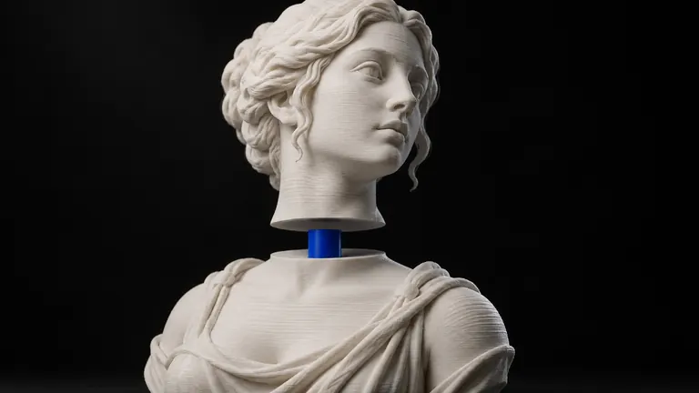
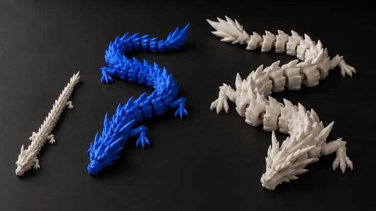
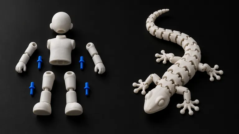
The figure printed beautifully. The first arm snapped in with a satisfying click. The second arm split the socket. The head went in fine and a week later it nods at the floor. Three joints, three outcomes, one printer, and nothing in the file said which would happen.
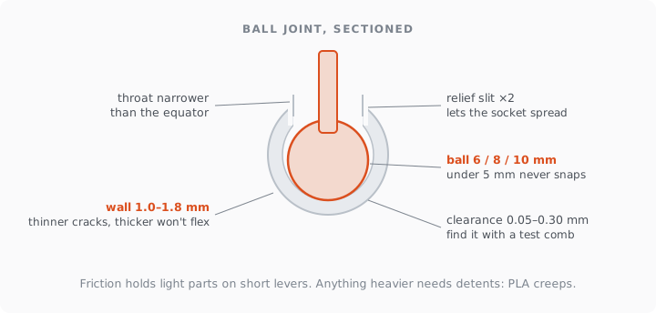
Short version: a printed ball joint is a ball, a socket with a throat narrower than the ball's equator, and a wall thin enough to spread and thick enough not to crack, which on a 0.4 mm nozzle means 1.0 to 1.8 mm. Nothing below about 5 mm of ball diameter snaps reliably in FDM. And a joint held by friction alone will sag, because PLA creeps at room temperature; anything heavy or long needs detents.
The parts of a joint that works
A socket is not a spherical hole. It is a sphere with an opening narrower than the ball's widest point, so the ball has to force its way past the throat and is then held behind it. For the throat to open at all, the socket needs somewhere to flex: two thin slits cut into the rim, opposite each other, let the two halves spread during insertion and spring back after. Without slits the ball goes in only if the clearance is so large that it falls out again.
The wall around the socket is where most designs fail. We use a 1.0 to 1.8 mm window for a 6 to 10 mm ball printed with a 0.4 mm nozzle: below 1.0 mm the socket cracks on the first insertion, above 1.8 mm it has no give and the ball never enters. General snap-fit guidance points the same way, a base of at least 1 mm with a generous fillet where the flexing wall meets the body (Protolabs Network snap-fit guide). Around a socket that carries load, keep 1.2 to 1.6 mm of solid material outside the socket wall, and around a thread 2 mm, because a thread pushes outward all the way around.
Which means the joint has to fit inside the part. A 6 mm ball needs a socket of roughly 6 + 2 × 1.2 = 8.4 mm of material in every direction. If the wrist is 7 mm thick, there is no legal socket in that wrist; the honest answer is a smaller ball, swapping which side is male, or fusing the hand to the forearm. A socket forced into a part that is too thin doesn't fail in the design, it fails on the plate, as a hole through the side of the arm.
Sizes: three classes, not a continuum
| Ball diameter | Socket wall | Holds a pose by friction up to | Typical placement |
|---|---|---|---|
| under 5 mm | any | never snaps reliably | don't; fuse the parts |
| 6 mm | 1.0–1.2 mm | a hand, a tail tip | wrists, ankles, small heads |
| 8 mm | 1.2–1.5 mm | a forearm, a small head | elbows, necks on 120–180 mm figures |
| 10 mm | 1.5–1.8 mm | an upper arm, a leg | shoulders, hips |
The friction column is a working rule from our own prints, not a table from a handbook, because no handbook tabulates friction of printed PLA on printed PLA. Our current figure is that friction alone holds a pose up to roughly 15 to 20 g on a short lever; beyond that the joint needs a mechanical stop. We quantize to three sizes on purpose. Every socket of the same class is interchangeable, so a head generated today fits a body generated next month, and a calibration done once applies to all of them.
Why the head nods at the floor after a week
Friction depends on the socket squeezing the ball. PLA under a steady load does not hold that squeeze: it creeps, slowly deforming at room temperature, measurably more than ABS in the same test (Dogan et al., creep of FDM PLA at 25 °C, 2022). A socket that was tight on day one relaxes over days, and a pose that was held by friction sags.
There is a deeper reason too: a smooth sphere in a smooth socket cannot be locked by pressure at all, because a sphere slides on itself in every rotation. Something has to break that smoothness. The toy industry's answer is detents: shallow grooves on the ball and small bumps in the socket that give a set of positions with an audible click. Geometry doesn't creep. We use eight positions per rotation on joints that carry weight, and plain friction only on light parts far from the body. Model-kit makers solve the same problem with a third, softer part between the two hard ones, the polyethylene poly-cap inside a Gunpla joint (poly-cap); in a single-material print, the detent does that job.
Clearance is a direction, not a number
A ball printed lying down and the same ball printed standing up are different objects. Layers give the vertical direction a stepped surface and the first layers spread outward, the elephant foot, by 0.1 to 0.4 mm (Prusa compensation guide). The horizontal plane is smooth and accurate. So the clearance between ball and socket has one value in XY and another in Z, and a joint designed with one number fits in one orientation and jams in the other. The general fit table, which is written for round pegs in round holes, is in tolerances and clearances →; ball joints sit at the tight end of it and need the extra Z allowance.
Orientation also decides whether the slits survive. A printed part across its layers holds only a fraction of its in-plane strength; one measured set for PLA is 35.5 versus 55.5 MPa, about 64% (Eryildiz, 2021). The two socket halves flex every time the ball goes in, so that flex must run along the layers, not try to peel them apart. Print the socket with its opening facing up or sideways, never with the slits stacked through the layers. More on which way up in orientation and strength →.
The one print that tells you the real clearance
Every number above is a starting point. The real clearance for your printer, your filament and your orientation is unknown until you print it, because it depends on nozzle wear, flow calibration, cooling and the material. The way to learn it is a test comb: six sockets in a row with clearances stepping from 0.05 to 0.30 mm, and a matching ball. Print it once, lying and standing, in each material you use. The socket that snaps firmly and rotates without cracking is your number; write it down per material.
A public one to start from is the Ball Joint Calibration on MakerWorld. Our own comb adds notched balls in three sizes so the same print also measures how much friction each class actually holds, and the results feed a table per printer and material that the constructor we're building reads when it sizes a joint. Until you have run a comb, treat every ball-joint clearance you read online, including ours, as an educated guess.
Hiding the joint
The naive way to add a joint to a figure is to cut out a thick slab and put an engineering ball and socket in the gap. It works and it looks terrible: half the head is missing and the socket bulges out of the shoulder. The alternative is to make the cut thin, 1.2 to 1.3 mm, and shape the end of the part as a dome centered on the ball, so the silhouette doesn't change when the joint rotates. The ball and socket sit fully inside the two parts. The price is range: about ±15 to 25° of tilt instead of ±35°, which for a posable figure is the right trade. Where the cut itself should go so the seam disappears is in where to cut a 3D model →.