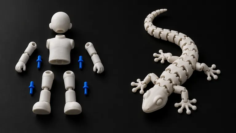
The articulated crystal dragon on MakerWorld has tens of thousands of boosts and prints perfectly at the size the designer uploaded. You scale it to 60% for a keychain and the segments come off the plate as one stiff bar. Someone else scales it to 180% for a shelf piece and it hangs like a wet noodle. Same file, same printer, nothing wrong with either.
Short version: the gap inside a joint is a fixed number of millimeters chosen for a specific size. Scaling the file scales that gap. Shrink it and the gap drops below what a nozzle can leave open, so the parts fuse; enlarge it and the gap grows past what friction can hold, so they flop. The joint has to be regenerated at the final size, not scaled with the model.
The arithmetic
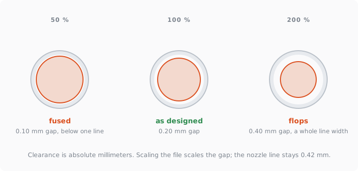
A print-in-place hinge or a chain segment is designed with a clearance in the neighborhood of 0.2 mm per side, the sliding-fit range for PLA (the fit table →). That number is not a percentage of the model. It is the smallest gap a 0.42 mm line of plastic will leave open after the elephant foot spreads the first layers and the layers above bond sideways to their neighbors.
| Scale | Design gap of 0.20 mm becomes | What happens |
|---|---|---|
| 50% | 0.10 mm | below the fusing threshold, segments weld on the plate |
| 75% | 0.15 mm | borderline; fuses in Z, may free up in XY with force |
| 100% | 0.20 mm | as designed |
| 150% | 0.30 mm | loose fit, holds no pose |
| 200% | 0.40 mm | rattles; a 0.4 mm gap is a whole line width |
The clearances article makes the same point for pegs and holes: a 200 mm part needs the same 0.2 mm sliding gap as a 20 mm one. Joints are the case where people find that out the hard way, because a joint is nothing but clearances.
Why shrinking is worse than enlarging
Two effects gang up on a scaled-down joint. First, the gap shrinks proportionally, from 0.20 to 0.10 mm at half scale. Second, the things that eat the gap don't shrink at all: the first layer still spreads by its 0.1 to 0.4 mm of elephant foot (Prusa's guide), the nozzle still lays a 0.42 mm line, and the layer above a gap still sags into it by the same fraction of a layer height. A gap that was comfortably twice the disturbance is now smaller than the disturbance. That is why the failure is not "a bit stiff" but "one solid piece".
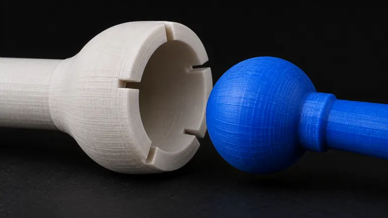
Enlarging fails more gently. A 0.4 mm gap still moves; it just no longer holds a pose, and on a ball joint it no longer snaps, because the throat that used to be 0.3 mm narrower than the ball is now barely narrower at all. The reasons a ball joint holds or doesn't are in ball joints that actually snap →.
What you can do with a file you didn't design
You have three levers in the slicer and none of them is a real fix. Bambu Studio's X-Y contour and hole compensation shrink or grow outlines by a fixed offset (Bambu wiki); a negative contour compensation of 0.05 to 0.1 mm can free a joint that scaled down to 75%, at the cost of thinning every wall in the model by the same amount. Elephant-foot compensation in the first-layer settings buys back another tenth at the plate. And a smaller layer height reduces how far the layer above a gap sags into it. Below about 70% scale, none of that is enough, and the model prints as one piece.
Enlarged models can sometimes be rescued by material: PETG's slightly higher friction, or a flexible filament for the connecting segments. Mostly the honest answer is to print at the designer's size, or at least within ±20% of it.
What you can do with a file you did design
Design the joint last, at the final size. Keep the seam positions with the model, since creases and necks scale with the shape (where to cut so the seam disappears →), but generate the connector geometry, ball diameter, socket wall, clearance, only once the print size is fixed. Every size then gets its own correct joint instead of a scaled copy of someone else's.
This is how the constructor we're building in PHORM works, and it's the reason it can exist at all: a generated model has no size until you give it one, so the pipeline already scales every model to real millimeters before anything else happens. Seam candidates are computed once and cached; joint geometry is regenerated for the final size and the target printer every time the size changes, and each piece goes through the same zero-warning check as a single model. A static STL cannot do that, which is why every articulated file on a model site comes with a line that says "print at 100%".