Two printed parts modeled to identical dimensions will not fit together. Not because something failed — because a nominal-size pin in a nominal-size hole has zero clearance, and zero is not a fit. Every part that mates with another part needs a designed gap.
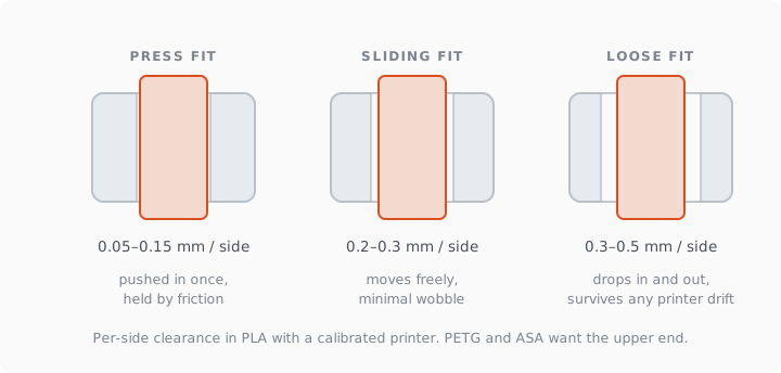
Short version: in PLA on a calibrated printer, use about 0.1 mm of clearance per side for a press fit, 0.2–0.3 mm for a sliding fit, and 0.3–0.5 mm for a loose fit. When in doubt, print the ten-minute tolerance test once and know your machine's real numbers forever.
The fit table
Numbers are clearance per side (radius, not diameter), for PLA on a well-calibrated FDM printer; they synthesize published design guides (Sovol's tolerance guide, a university fab-lab standard, Hubs' enclosure rules).
| Fit | Clearance per side | Feels like | Use for |
|---|---|---|---|
| Press fit | 0.05–0.15 mm | firm push, stays put | pins, bearings, cosmetic caps |
| Snug fit | 0.15–0.2 mm | slides with friction | lids, sleeves, battery doors |
| Sliding fit | 0.2–0.3 mm | moves freely, minimal play | hinges, drawers, telescoping parts |
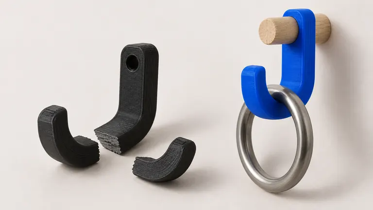
| Loose fit | 0.3–0.5 mm | drops in and out | hooks, hanging parts, print-in-place |
| Screw clearance hole | +0.25 mm on diameter | screw passes freely | M3–M5 fasteners (Hubs) |
Adjustments that move the whole table: PETG and ASA want the upper end of each range (stringier, more flow variation); a printer you haven't calibrated wants +0.1 mm everywhere; parts taller than wide accumulate more error; and holes behave worse than pins, for reasons below.
Why printed holes run small
Three stacked effects. First-layer squish spreads the bottom perimeter inward (elephant foot, Prusa's explanation — around 0.2 mm of it on a default 0.4 mm nozzle). Perimeter corners round off inside curves. And cooling shrinkage pulls hole walls inward from every side, per material — the shrinkage numbers →. The standard answers: use the slicer's X-Y hole compensation (Bambu suggests 0.05 mm for PLA, 0.1 for PETG/ABS as starting points), or for a truly critical vertical hole, print undersized and drill to size, which is Hubs' standing recommendation for a reason.
Calibrate once: the tolerance test
Every printer, filament and profile combination has its own truth. Print any of the standard tolerance test models (pegs and holes with 0.1–0.5 mm gaps, ten minutes of print time), and note which gap gives which feel on your machine. Those three numbers replace this entire article for your workshop. Recheck when you change nozzle, material brand, or slicer profile.
Tolerances in the photo-to-part workflow
A part reproduced from a photo faces every tolerance at once: the reconstruction guesses dimensions (fix that with one caliper measurement →), the print adds its own error, the material shrinks. The workflow that survives all three is scale-verify, add clearance by the table, print, test-fit, adjust once. One iteration is normal engineering, not failure; the complete sequence is in the photo-to-print guide →. And clearances only mean anything on a mesh whose dimensions are trustworthy: PHORM prints exact model dimensions in every validator report, so the number you add clearance to is real — generate from a photo and check the report →.
What FDM cannot promise
Sub-0.1 mm repeatable tolerances are thread-cutting territory, not desktop FDM. Threads that mate with factory bolts: model the clearance hole and use a metal insert or cut the thread with a tap. Bearing seats and sub-0.05 fits: print, then drill or ream. Designing around the printer's real ±0.15–0.2 mm accuracy beats fighting it; AON3D's engineering-fit guide frames clearance as one or two extrusion widths, which is the same table in different units.