You have a photo of a thing — a broken bracket, a discontinued knob, an object you want to reproduce — and a 3D printer. Between those two points there are exactly three real routes, and most guides only tell you about the one they're selling. Here's the honest map, then a deep dive into the fastest route with the technique that separates a usable part from a melted blob.
The three routes, honestly compared
| Photogrammetry (many photos) | AI image-to-3D (one photo) | Manual CAD remodel | |
|---|---|---|---|
| Input | 30–100 photos around the object | 1–3 photos | measurements + skill |
| Time to printable | 1–3 hours | minutes + repair (or not — see below) | 1–8 hours |
| Dimensional accuracy | good, after scaling | approximate → good with calibration | as good as your calipers |
| Geometry it can't see | struggles with shiny/thin | invents hidden sides | none — you model everything |
| Skill required | moderate | low | high (CAD) |
| Best for | organic shapes, art, scans of sculpture | fast reproduction, household parts, prototypes | precision engineering parts, threads |
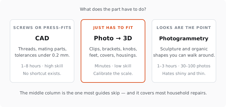
Rules of thumb: threads, press-fits and sub-0.2 mm tolerances → CAD, no shortcuts exist. Organic sculpture you physically own and can walk around → photogrammetry. Everything in between — the broken clip, the missing foot, the discontinued holder — is where the AI route wins on time, if you handle the three gotchas below.
The AI route, step by step
Step 1: Take a photo the reconstruction can use
The single highest-leverage minute of the whole workflow — it has a dedicated deep dive →, and the short version follows. The generator can only reconstruct what it can see and infer — feed it ambiguity and it will confidently invent geometry.
- Angle: three-quarter view showing three faces of the object beats a straight-on mugshot. If the tool accepts multiple photos, add a top view.
- Light: diffuse daylight, no harsh shadows — shadows read as geometry to reconstruction models.
- Background: plain and contrasting. Busy backgrounds leak into the mesh as noise.
- The whole object in frame, nothing cropped: cropped edges become hallucinated geometry.
- Matte over shiny: glare defeats reconstruction. Dust a chrome part with chalk or shoot it under a cloth diffuser.
Step 2: Generate — and understand what you got
Any image-to-3D tool gives you a mesh. What matters for printing is what's in that mesh: reconstruction artifacts — non-manifold edges, zero-thickness walls, holes on the sides the photo didn't show. We catalogued all six failure modes in why AI models fail to print →; the short version is that a raw generated mesh is a draft, not a part.
From here the route forks. Generic generators (Meshy, Tripo and friends) hand you the draft — repair is your job, in Blender or the slicer, 20–60 minutes for a typical model. A print-first pipeline does the repair inline: PHORM runs mesh repair and a printability verdict on every generation — if it fails the check, it doesn't count and you retry free; if it passes, the file that lands in your slicer opens with zero warnings. 2 free models to start, no card →
Step 3: Calibrate the scale — the step everyone skips
An STL has no units, and a photo has no absolute size. Every photo-to-print failure story that ends with "it came out 60% too small" skipped this step.
The discipline (expanded with slicer-by-slicer steps here →): measure one reference dimension on the real object with calipers — the longest edge, a hole diameter, anything unambiguous. In the slicer, scale the model until that dimension matches. One measurement locks all three axes (uniform scale); for parts that must mate with other parts, verify a second dimension perpendicular to the first — photo reconstruction can stretch one axis slightly. Fits also need designed gaps on top of true size: the clearance table →.
Step 4: Choose the material for the job
- PLA — dimensionally the most predictable (lowest shrinkage), stiff, easy. Default for indoor, low-stress parts. Softens in a hot car.
- PETG — tougher, slightly flexible, handles outdoors and moisture. Shrinks a touch more; strings if your profile is lazy.
- ABS/ASA — heat and UV resistance for parts near engines, radiators, sunlight (shrinkage numbers per material →). Meaningful shrinkage: an enclosed printer (Bambu P1S/X1C class) and, for accuracy-critical parts, shrinkage compensation — dialed in manually, or automatically on PHORM's Studio plan.
Step 5: Print settings for parts, not figurines
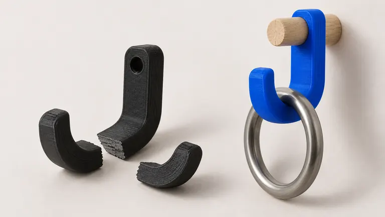
Functional parts flip the usual priorities: walls over infill (4 perimeters at 25% infill beat 2 perimeters at 60% for strength per gram), orient layers across the load → (a hook printed flat snaps along layers; printed on its side it holds), 0.2 mm layers are plenty, and slow the first layer for anything with small contact area.
Step 6: Test-fit, adjust, reprint
For a part that mates with something: print, test-fit, adjust scale or clearance (0.2–0.3 mm gap for sliding fits in PLA), reprint. One iteration is normal; the photo route's superpower is that iteration costs minutes and grams, not another CAD evening.
What photo-based reconstruction can and can't deliver
Can: overall shape faithful to a few percent, correct proportions, printable organic and boxy geometry, parts that fit after one calibration-and-test cycle. Can't: threads that screw onto factory bolts, internal geometry the photo never saw, guaranteed sub-0.2 mm tolerances, text engraving legible below ~8 mm. Treat those as CAD territory — or hybrid: generate the body from a photo, add the precision feature in a CAD tool on top.
Not sure which parts around the house are worth the effort? We put together a catalog with the filament each one needs: 30 household parts to print instead of rebuying →